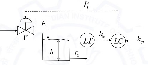
The process and instrumentation diagram for a feedback control strategy to maintain the level $(h)$ of a liquid by regulating a valve $(V)$ in a tank is shown below. $F_1$ is inlet liquid flow rate, $F_2$ is outlet liquid flow rate, $LT$ is the liquid level transmitter, $LC$ is the liquid level controller, $h_{sp}$ is the setpoint value of the liquid level, $h_m$ is the measured value of the liquid level and $P_v$ is the valve pressure.
The manipulating variable(s) is/are
- $F_1$ only
- $F_2$ only
- $h_m$ and $P_v$ only
- $h_{sp}$ and $P_v$ only